Key Radio KM Series
Amateur Conversion Information


by Tom Grady G6IGA keyradioatsuperiorsignals.co.uk copyright 1998-2022

All registered trademarks are acknowledged
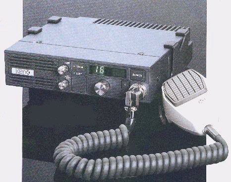
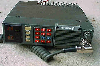
Key KM150 (KG105) Radio


The Key (Kyodo) Radio is an extremely versatile PMR or trunked radio set, which can be converted and utilised for many amateur radio bands (70cm,2m,4m).
        Key KM450 Service Manual in pdf format
  • Link to Key KM450 Service Manual in pdf format size 137 Megs 144 pages

    Starting to convert the Key KM Series Radio

  • As the set is modular in its construction, many combinations can be added or removed as necessary.
    Most of the general conversion & programming information is covered on these pages but will continue to develop as time goes by.
  • Before anything can be set up the first thing that must be configured is the 2732 eprom which holds the frequency information located on the top right hand PLL (Phase Locked Loop) board.


  • Programming the frequencies into the 2732 eprom

  • PLEASE NOTE: I am not able to supply parts, only answer questions about KEY KM series radios ! (I'm always hunting for Key bits myself though)

  • Hopefully readers of this article will be familiar with how to actually program a 2732 eprom, the information below purely describes how to calculate the frequency information to go into the 2732.
  • Please contact epromsatsuperiorsignals.co.uk for pre-programmed devices @ GBP 11.45 UK pounds (inc GBP 1.45 UK postage) / 13.00 Euros each (inc GBP 4.25 international postage) postage (Please note as 2732 eproms are no longer manufactured, the devices MAY be recycled ones). 6.45 GBP UK pounds (inc GBP 1.45 UK postage) / 7.50 Euros (inc GBP 4.25 international postage) each if you supply the blank devices.
  • Each line of code in the eprom consists of the TX freq / Reference division rate (step size) / RX freq / Reference division rate (step size).


  • Now the maths to do it

  • A number of parameters need to be worked out;

  • The 12MHz TCXO is divided by 16 (IC101) to provide a 750KHz Reference Frequency. This reference frequency is sampled and divided by the 'Reference Division Rate' to determine the channel spacings.

  • Reference Division Rate - 750KHz/12.5KHz = 60 = C30 in reversed Hex as used by the Key (see TX(R) & RX(R) in the table below).

  • Reference Division Rate - 750KHz/10KHz = 75 = B40 in reversed Hex as used by the Key (see TX(R) & RX(R) in the table below).

  • Each Address code ALWAYS starts with F i.e. F* F* F* so that for the reference division rate for 12.5KHz C30 works out to be FC F3 F0.

  • D = Basic Division Rate = Frequency of operation / 12.5

  • d = Prescaler Division Rate fixed at 64

  • N = Number of Complete Divisions

  • R = Remainder of the Basic Division Rate

  • 'N' & 'A' are calculated using the following equation; D = ( N x d ) + A / works out to the following in the example below
    11.602 = (0.181 x 64) + 0.018

  • A TX frequency of 145.025MHz = 145.025/12.5 = 11.602 = D then divided by d (fixed at 64)

  • 11.602/64 = 0.18128125 = 0.181 Number of complete divisions = N = 181 converted into Hex and reversed = 5B0 (see TX(N) in the table below).

  • 0.181x64 = 11.584-11.602 = 0.018 = A = Remainder of the basic division rate

  • 18 converted into Hex and reversed = 21 (see TX(A) in the table below).

  • Receive is similar BUT 21.6MHz has to be taken off the RX frequency

  • A RX frequency of 145.625MHz = 145.625-21.6/12.5 = 9.922/64 = 0.15503125

  • 0.155 Number of complete divisions = N = 155 converted into Hex then reversed B90 (see RX(N) in the table below).

  • 0.155x64 = 9.92-9.922 = 0.002 = A = Remainder of the basic division rate

  • 2 converted into Hex and reversed = 20 (see RX(A) in the table below).


Key 2732 Eprom Coding
Channel #1 Address01234 56789AB CDEF
TX(A)
TX(N)
TX(R)
RX(A)
RX(N)
RX(R)
Channel Data - example 145.025 Tx 145.625 RxF2F1F5FB F0FCF3F0F2F0FBF9 F0FCF3F0
Channel #2 Address1011121314 15161718191A1B 1C1D1E1F
TX(A)
TX(N)
TX(R)
RX(A)
RX(N)
RX(R)
Channel Data - example 145.050 Tx 145.650 RxF4F1F5FB F0FCF3F0F4F0FB F9F0FCF3F0


    This is the easy bit ... some preconfigured files to blow straight into a 2732 Eprom

  • 70cms eprom binary code - 70cms 80 channel RB0-RB15 repeaters, simplex, packet (reverse repeaters, internet linking and Low Power Repeaters in 2nd 40 bank) Channel Listing

  • 70cms eprom binary code - 70cms 32 channel RB0-RB15 repeaters, (Simplex and Low Power Repeaters in 2nd 16 bank) Channel Listing

  • 70cms eprom binary code - 70cms 16 channel RB0-RB15 repeaters Channel Listing

  • 70cms eprom binary code - 70cms 16 channel internet linking frequencies Channel Listing

  • 2 Metres eprom binary code - 2 metres 80 channel ( 40 channels + reverse repeater in 2nd 40 bank) Channel Listing

  • 2 Metres eprom binary code - 2 metres 80 channel (new 12.5 Khz spec + reverse repeater) Channel Listing

  • 4 Metres eprom binary code - 4 metres 40 channel ( all 12k5 channels ) Channel Listing

  • 4 Metres eprom binary code - 4 metres 16 channel ( 16 channels ) Channel Listing
  • Pete Baston's / Richard Newton G0EWH - Key KM150 and 450 eprom code generator program this is for generating your own frequencies / codes (coding not valid on other models!)

  • Pete Baston's Key KM80 eprom code generator program this is for generating your own frequencies / codes (coding not valid on other models!)

  • Pete Baston's Ericsson Kyodo KG107 eprom code generator program this is for generating your own frequencies / codes (coding not valid on other models!) please note this picture is here purely for reference, this page does not cover conversion of this model


  • Ericsson Kyodo KG107 Radio

    Once a programmed eprom has been fitted - alignment of set

  • Important see circuit layout located on reverse of the top lid for location of components.

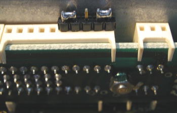
  • Make sure a shorting link (made from 5 x 0.1" pin header - CPC Order No.CN00870 or Maplin Order No. JW59P) is in place between pins 25 & 24 (audio) and 22 & 21 (PTT) if a option board i.e. CTCSS or 5-Tone board is not present on the front interfacing connector.

  • Without it you will not get any audio or PTT keying

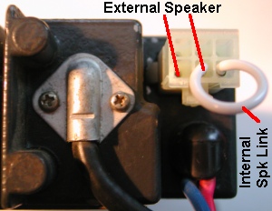
  • Additionally you may also need the speaker linking plug fitted to the rear of the radio - again no audio without it


  • Key Shorting Link

  • Set radio as near to the middle channel as possible for best alignment (Maximum difference between highest and lowest channel is approx 8 to 10MHz).

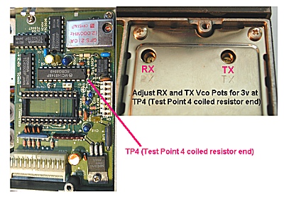
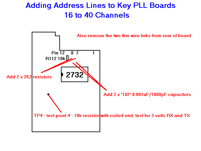
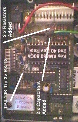
  • Connect a voltmeter to Test Point 4 (see adding address lines diagram below) adjust the two VCO trimmer capacitors marked RX and TX, on the opposite side of the set through the covering plate. Look for 3 volts in both RX and TX mode (press PTT for TX mode the LED should light when the VCO has locked). If you do not get the results expected, have you removed the two thin wires sometimes mounted on the reverse side of the board behind the eprom socket.


  • Key VCO Adjustment

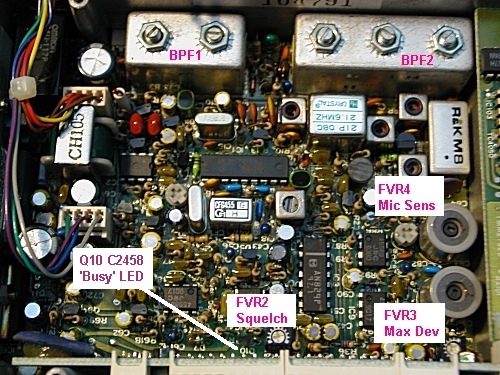
  • Adjust BPF1 (2 cores) & BPF2 (3 cores) the large Band Pass filters on the main board at the back of the set for best receive performance, the rest of the receiver L3,L2,T1,T2,T3 (IF section),FVR1 (max volume setting pot 5w/8ohms) should NOT need ANY adjustment.

  • Adjust FVR2 for the most suitable squelch opening point normally -119dBm for 12 Sinad.

  • Adjust FVR4 to maximum microphone sensitivity but LIMIT the overall TX deviation to 5KHz (25KHz system) or 2.5KHz (12.5KHz system) with FVR3.


  • Key RF Board Adjustments

  • To set final RX & TX frequency TCXO in top right hand corner of PLL board.

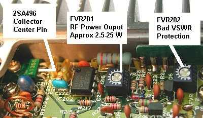
  • By removing the small screws underneath the PA section access to the PA compartment can be made, to adjust the transmit power level between 2.5 and 25 watts plus. It is important to correctly adjust the power protection circuit correctly, or otherwise damage to the PA can occur with a bad aerial load. FVR201 adjusts the output power, FVR202 adjusts the ALC power protector (Bad VSWR protection). To correctly set the output power, with a meter & dummy load attached, adjust FVR201 to 1/2 power about 12.5 watts. Read the collector voltage of transistor 2SA496 (top left corner of PA 'check' test pin) around 6 volts. Now remove the dummy load, adjust FVR201 back to maximum power, but adjust FV202 to limit it back down to the voltage you had previously. Replace the dummy load and adjust FVR201 to the maximum power you require without altering FVR202 again.

  • Replace PA cover.


  • Key PA Section Adjustment


    Fitting the extra goodies

    Adding a squelch pot to 40 channel trunk head

  • Remove top & bottom lids.

  • Remove 2 x large screws from sides of control head, Remove 6 x silver screws from brown PCB in back of head.

  • Be careful NOT to damage flexitrack when lifting up PCB.

  • Unsolder 2 white speaker leads from underside of PCB, remove white sleeving & cardboard insulator.

  • Remove 2 x standoff posts and locking screw in the middle of the PCB.

  • Remove 2 x screws from rear of power switch, ping off power switch cap with a knife.

  • Undo locking ring & washer around microphone socket.

  • Using allen keys remove the channel & volume knobs.

  • Unbolt the volume pot from PCB, be VERY careful with the flexitrack!

  • Remove 4k7 resistor from the small volume/squelch pot PCB.

  • Remove plastic blanking plug.

  • Add squelch pot, solder to PCB and bolt back in.

  • Reassemble.


  • Adding address lines to Key PLL board to increase set from 16 to 40 channels

  • Important - please do not start this modification unless you have a 40 channel trunking control head available

Key 40 channel Head

Key 16 channel Head


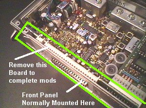
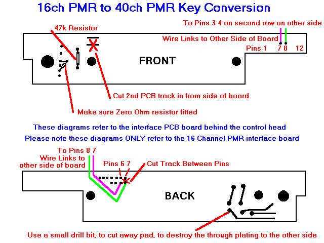
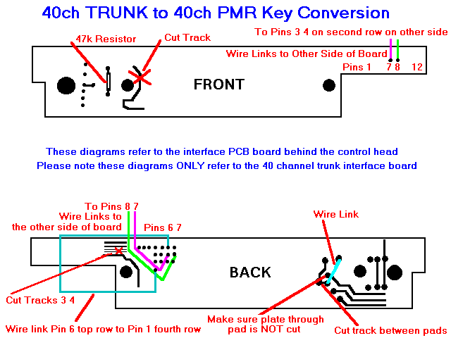
  • By swapping the control head from a 40 channel trunked radio, to a 16 channel PMR set, the following modifications will allow full 40 channel coverage of the amateur bands.
  • The diagram below also shows how to add two extra address lines to the PLL board to allow 40 channel operation instead of 16 channel working.

  • Fit 2 x 2k2 and 2 x '102' capacitors in the location show, remove the two thin wire links from the rear of the PLL board

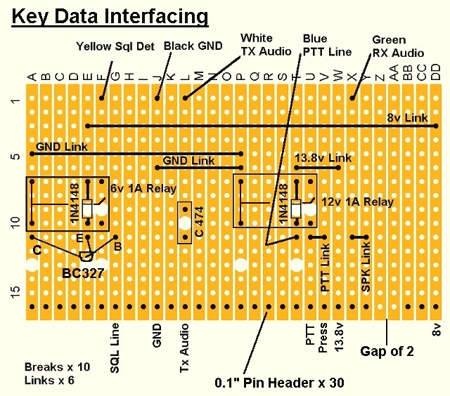
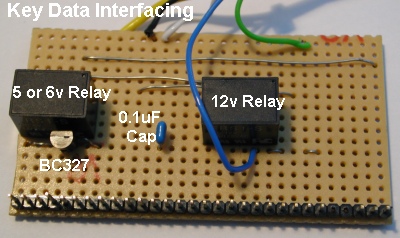
  • Of course you will ALSO have to carry out the modifications to the interface board described next.


  • Key PLL Board

    Key PLL Board


    Details of additional facilities modules

    Board with 6303 processor + FX419 FSK decoder

  • Band 3 trunking signalling board made by

    Fylde Microsystems Ltd
    8 Avroe Crescent
    Blackpool Business Park
    Blackpool
    Lancs
    FY4 2DP

    (01253) 407040

    - marked with label in format '002/01/0*****' - the Electronic Security Number (ESN) label.


  • CT1 CTCSS original analogue module

  • VR 1 - CTCSS frequency.

  • VR 2 - Output level.

  • VR 3 - Level of warble.

  • Link 1 - Mic hookswitch monitor.

  • Link 2 - Unkey delay for squelch tail elimination.

  • Link 3 - Carrier lockout for repeater operation.

  • Link 4 - PTT timer.

  • Link 5 - Warble tone.


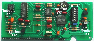
  • CT4 CTCSS updated digital module

  • VR 1 - Output level.

  • Link 1 - Repeater lockout.

  • Link 2 - Time out timer.

  • Link 3 - Monitor switch deactivate.


    Below is the chart to select the correct CTCSS tone on the CT4 & the ST1A/ST2A tone boards

CTCSS Tone Chart
Switch123456
67.0111111
71.9011111
74.4111110
77.0001111
79.7111101
82.5011110
85.4111100
88.5001110
91.5111011
94.8011101
97.4111010
100.0001101
103.5011100
107.2001100
110.9011011
114.8001011
118.8011010
123.0001010
127.3011001
131.8001001
136.5011000
141.3001000
146.2010111
151.4000111
156.7010110
162.2000110
167.9010101
173.8000101
179.9010100
186.2000100
192.8010011
203.5000011
210.7010010
218.1000010
225.7010001
233.6000001
241.8010000
250.3000000


    ST1A/ST2A Link programmable 5-Tone + CTCSS module

  • 5-Tone module (model S1503 - selcall en/decoder) part of this unit is manufactured by Sigtec

  • VR1 - CTCSS deviation.

  • VR2 - Alert tone level.

  • Link 1 - Make for No CTCSS lockout.

  • Link 2 - Make for no time out timer.

  • Link 3 - Make for no CTCSS monitor.

  • Link 4 - Make for display On.

  • Link 5 - Make for display off, flashing off when called.

  • Link 6 - Make for display on flashing off when called.

  • Link 7 - Make for no TX when RX muted by selcall.

  • Note Make either LK4,5,6 or if none are made the display is off. (LK6 made when supplied)

  • TS - Tonesets (0)CCIR (1)EEA (2)EIA (3)ZVEI-1 (4)ZVEI-2 (5)ZVEI-3 (6)NATEL

  • TP - Tone Period (0)20ms (1)33ms (2)40ms (3)70ms (4)100ms

  • LD - Lead In Delay (N/C)500ms (0)100ms (1)200ms (2)500ms (3)1000ms (4)2000ms

  • R1,R2,R3,R4,R5 - Receive Code

  • T1,T2,T3,T4,T5 - Transmit Code

  • R1,R2,R3,T1,T2,T3 - Selected by wire links

  • R4,R5,T4,T5 - Selected by solder bridging network

  • B - Phase of decode output can be reversed by solder bridging point marked 'B'


  • ST3 Eprom programmable 5-Tone module


  • Made to order unit for the JRC power industries band, no details of programming available from Key Radio or JRC.


  • Links

  • OH3TR Tampere University of Technology Ham Radio Club Key 450MHz handportable (KC450HT) modifications from Finland


  • IW1PUR Italian Key Radio Conversion Page This page goes international translated into Italian


  • by Tom Grady G6IGA keyradioatsuperiorsignals.co.uk copyright 1998-2022


    GobackBack to Home Page